Nissan Juke Service and Repair Manual : CVT shift selector
Exploded View
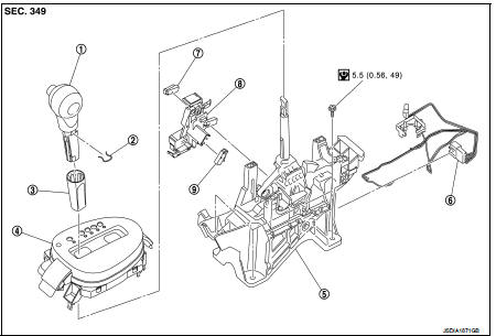
1. Selector lever knob
2. Lock pin
3. Knob cover
4 Position indication panel
5. CVT shift selector assembly
6. CVT shift lock unit
7. Key interlock rod*
8. Indicator lamp
 :N·m (kg-m, it-lb)
*: Without push engine starter
Removal and Installation
REMOVAL
CAUTION:
Always apply the parking brake before performing removal and installation.
1. Disconnect battery cable from negative terminal. Refer to PG-124, "Removal and Installation".
2. Shift the selector lever to “N” position.
3. Remove the center console. Refer to IP-23, "Removal and Installation".
4. Disconnect the CVT shift selector connector.
5. Shift the selector lever to “P” position.
6. Remove the key interlock cable from the CVT shift selector assembly. Refer to TM-276, "Removal and Installation" (Without push stater system).
7. Remove the control cable from the CVT shift selector assembly. Refer to TM-273, "Removal and Installation".
8. Remove the CVT shift selector assembly.
INSTALLATION
Note the following, and install in the reverse order of removal.
• When connecting the control cable (1) to the CVT shift selector assembly (2), face the grooved surface of the rib (A) up and insert the control cable until it stops.

Disassembly and Assembly
DISASSEMBLY
1. Slide the selector lever knob cover (1) down.
CAUTION:
Never damage the knob cover.
2. Pull out the lock pin (2).
3. Pull the selector lever knob (3) and knob cover upwards to remove them.
4. Remove the position lamp.

5. Disengage the hooks (A) (4 locations), and lift up the position indication panel (1) to separate it from the CVT shift selector assembly (2).
CAUTION:
Never damage the CVT shift selector assembly.

6. Shift the selector lever to “N” position.
7. Remove the shift lock unit from the CVT shift selector assembly.

INSTALLATION
Note the following, and install in the reverse order of removal.
• Follow the procedure below and place the selector knob onto the CVT shift selector.
1. Install the lock pin (2) onto the selector lever knob (3).
2. Install the knob cover (1) onto the selector lever knob.
3. Press the selector lever knob onto the selector lever until it clicks.
CAUTION:
• When pressing the selector lever knob onto the selector
lever, never press the selector lever knob button.
• Never strike the selector lever knob to press it into place.

• Follow the procedure below and press the shift lock unit onto the CVT shift selector.
1. Connect the connectors.
2. Install the shift lock unit.
Inspection
INSPECTION AFTER INSTALLATION
Check the CVT position. If a malfunction is found, adjust the CVT position. Refer to TM-194, "Inspection and Adjustment".

 Control cable
Exploded View
1. Control cable
2. Lock plate
3. Transaxle assembly
4. Bracket A
5. Bracket B
6. CVT shift selector assembly
A: Manual lever B: Grommet
: N·m (kg-m, ft-lb)
: N·m (kg-m, i ...
Other materials:
Tow Truck Towing
CAUTION:
• All applicable state or Provincial laws and local laws regarding the towing
operation must be
obeyed.
• It is necessary to use proper towing equipment to avoid possible damage to the
vehicle during towing
operation. Towing is in accordance with Towing Procedure Manual at dealer.
...
P1726 throttle control signal
Description
Electric throttle control actuator consists of throttle control motor,
accelerator pedal position sensor, throttle
position sensor etc. The actuator sends a signal to the ECM, and ECM sends the
signal to TCM with CAN
communication.
DTC Logic
DTC DETECTION LOGIC
DTC CONFIRMATI ...
Precaution for Seat Belt Service
CAUTION:
• Before removing the front seat belt pre-tensioner assembly, turn the ignition
switch off, disconnect
battery negative terminal and wait at least 3 minutes.
• Do not use electrical test equipment for front seat belt pre-tensioner
connector.
• After replacing or reinstalling front s ...
