Nissan Juke Service and Repair Manual : Cooler pipe and hose
Exploded View

1. A/C unit assembly
2. O-ring
3. High-pressure pipe
4. Condenser
5. Low-pressure flexible hose
6. O-ring
7. Compressor
8. O-ring
9. High-pressure flexible hose
 : Do not reuse
 : N·m (kg-m, in-lb)
 : N·m (kg-m, ft-lb)
High-pressure flexible hose : Removal and Installation
CAUTION:
Perform lubricant return operation before each refrigeration system disassembly.
However, if a large
amount of refrigerant or lubricant is detected, never perform lubricant return
operation. Refer to HA-
23, "Perform Lubricant Return Operation
".
REMOVAL
1. Use a refrigerant collecting equipment (for HFC-134a) to discharge the refrigerant. Refer to HA-21, "Recycle Refrigerant".
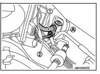
2. Remove mounting bolt (A), and then disconnect high-pressure flexible hose from condenser.
CAUTION:
Cap or wrap the joint of the A/C piping and condenser with
suitable material such as vinyl tape to avoid the entry of air.

3. Remove mounting bolt (A), and then disconnect high-pressure flexible hose from compressor.
CAUTION:
Cap or wrap the joint of the A/C piping and compressor with
suitable material such as vinyl tape to avoid the entry of air.

4. Remove high-pressure flexible hose from vehicle.
INSTALLATION
Note the following items, and then install in the reverse order of removal.
CAUTION:
• Replace O-rings with new ones. Then apply compressor oil to them when
installing.
• Check for leakages when recharging refrigerant. Refer to HA-19, "Leak Test".
Low-pressure flexible hose : Removal and Installation
CAUTION:
Perform lubricant return operation before each refrigeration system disassembly.
However, if a large
amount of refrigerant or lubricant is detected, never perform lubricant return
operation. Refer to HA-
23, "Perform Lubricant Return Operation".
REMOVAL
1. Use a refrigerant collecting equipment (for HFC-134a) to discharge the refrigerant. Refer to HA-21, "Recycle Refrigerant".
2. Remove air duct. Refer to EM-161, "Removal and Installation".
3. Remove low-pressure flexible hose (1) mounting bolt (A), and nut (B).

4. Remove plastic nut, and then move lower dash insulator aside.
 : Plastic nut

5. Remove mounting bolt (A), and then disconnect low-pressure flexible hose (1) and high-pressure pipe (2) from expansion valve. Refer to HA-56, "EXPANSION VALVE : Removal and Installation".
CAUTION:
Cap or wrap the joint of the A/C piping and expansion valve
with suitable material such as vinyl tape to avoid the entry
of air.
6. Remove mounting bolt (A), and then remove low-pressure flexible hose (1) from compressor.
CAUTION:
Cap or wrap the joint of the A/C piping and compressor with
suitable material such as vinyl tape to avoid the entry of air.

INSTALLATION
Note the following items, and then install in the reverse order of removal.
CAUTION:
• Replace O-rings with new ones. Then apply compressor oil to them when
installing.
• Check for leakages when recharging refrigerant. Refer to HA-19, "Leak Test".
High-pressure pipe : Removal and Installation
CAUTION:
Perform lubricant return operation before each refrigeration system disassembly.
However, if a large
amount of refrigerant or lubricant is detected, never perform lubricant return
operation. Refer to HA-
23, "Perform Lubricant Return Operation".
REMOVAL
1. Use a refrigerant collecting equipment (for HFC-134a) to discharge the refrigerant. Refer to HA-21, "Recycle Refrigerant".
2. Remove air duct. Refer to EM-161, "Removal and Installation".
3. Remove low-pressure flexible hose (1) mounting bolt (A), and nut (B).

4. Remove plastic nut, and then move lower dash insulator aside.
 : Plastic nut

5. Remove mounting bolt (A), and then disconnect low-pressure flexible hose (1) and high-pressure pipe (2) from expansion valve. Refer to HA-56, "EXPANSION VALVE : Removal and Installation".
CAUTION:
Cap or wrap the joint of the A/C piping and expansion valve
with suitable material such as vinyl tape to avoid the entry
of air.

6. Remove mounting bolt (A), and then disconnect high-pressure pipe from condenser.
CAUTION:
Cap or wrap the joint of the A/C piping and condenser with
suitable material such as vinyl tape to avoid the entry of air.

7. Remove mounting bolt (A), and then remove ground wire (1) from engine unit.
8. Remove high-pressure pipe (2) fixing clips (B), and then remove high-pressure pipe.

INSTALLATION
Note the following items, and then install in the reverse order of removal.
CAUTION:
• Replace O-rings with new ones. Then apply compressor oil to them when
installing.
• Check for leakages when recharging refrigerant. Refer to HA-19, "Leak Test".
 Compressor
Exploded View
REMOVAL
1. High-pressure flexible hose
2. O-ring
3. Compressor
4. O-ring
5. Low-pressure flexible hose
A. To condenser
B. To evaporator
: N·m (kg-m, ft-lb)
DISASSEMBLY
...
 Condenser
Exploded View
1. Condenser
2. Refrigerant pressure sensor
3. O-ring
4. Grommet
5. Braket
6. O-ring
7. Liquid tank braket
8. Liquid tank
: Do not reuse
: N·m (kg-m, in-lb)
: N·m (kg-m ...
Other materials:
P0200 fuel injector
DTC Logic
DTC DETECTION LOGIC
Diagnosis Procedure
1.CHECK FUEL INJECTOR POWER SUPPLY CIRCUIT FOR OPEN AND SHORT
1. Turn ignition switch OFF.
2. Disconnect ECM harness connector.
3. Disconnect fuel injector harness connector.
4. Check the continuity between fuel injector harness connector an ...
U1010 control unit (CAN)
Description
CAN (Controller Area Network) is a serial communication line for real time
application. It is an on-vehicle multiplex
communication line with high data communication speed and excellent error
detection ability. Many electronic
control units are equipped onto a vehicle, and each co ...
B1131 side air bag module RH
DTC Logic
DTC DETECTION LOGIC
DTC CONFIRMATION PROCEDURE
1.CHECK SELF-DIAG RESULT
With CONSULT-III
1. Turn ignition switch ON.
2. Perform “Self Diagnostic Result” mode of “AIR BAG” using CONSULT-III.
Without CONSULT-III
1. Turn ignition switch ON.
2. Check the air bag warning lamp statu ...
