Nissan Juke Service and Repair Manual : Component parts
Meter system
METER SYSTEM : Component Parts Location
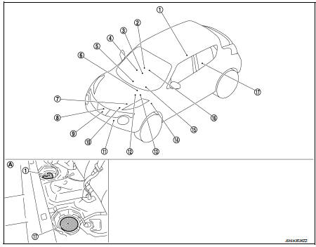
1. Fuel level sensor unit (main)
2. Front seat belt buckle switch (passenger
side)
3. CVT shift selector assembly
Refer to TM-131, "CVT CONTROL
SYSTEM : Component Parts Location"
(MR16DDT engine models).
Refer to TM-314, "CVT CONTROL SYSTEM : Component Parts Location" (HR16DE engine models).
4. Occupant detection unit (Under the passenger seat cushion pad) 5. A/C auto amp.
Refer to HAC-12, "Component Parts Location" (4WD models).
Refer to HAC-103, "AUTOMATIC AIR CONDITIONING SYSTEM : Component Parts Location" (2WD models).
6. ECM Refer to EC-455, "ENGINE CONTROL SYSTEM : Component Parts Location" (HR16DE engine models).
Refer to EC-813, "Component Parts Location" (K9K engine models).
7. IPDM E/R Refer to PCS-5, "Component Parts Location" (with I-KEY).
Refer to PCS-37, "Component Parts Location" (without I-KEY).
8. Oil pressure switch Refer to EM-103, "Exploded View" (MR16DDT engine models).
Refer to EM-227, "Exploded View" (HR16DE engine models).
Refer to LU-37, "Exploded View" (K9K engine models).
9. Oil level sensor Refer to EM-99, "Exploded View" (MR16DDT engine models).
Refer to EM-222, "Exploded View" (HR16DE engine models).
Refer to EM-330, "Disassembly and Assembly" (K9K engine models).
10. ECM Refer to EC-25, "ENGINE CONTROL SYSTEM : Component Parts Location" (MR16DDT engine models).
11. Ambient sensor Refer to HAC-12, "Component Parts Location" (2WD models).
Refer to HAC-103, "AUTOMATIC AIR CONDITIONING SYSTEM : Component Parts Location" (4WD models).
12. ABS actuator and electric unit (control unit) Refer to BRC-97, "Component Parts Location" (with ESP).
Refer to BRC-9, "Component Parts Location" (without ESP).
13. TCM
Refer to TM-131, "CVT CONTROL
SYSTEM : Component Parts Location"
(for RE0F10B models)
Refer to TM-314, "CVT CONTROL
SYSTEM : Component Parts Location"
(for RE0F11A models)
14. BCM
Refer to BCS-6, "BODY CONTROL
SYSTEM : Component Parts Location"
(with intelligent key system)
Refer to BCS-96, "BODY CONTROL
SYSTEM : Component Parts Location"
(without intelligent key system)
15. Combination meter
16. Front seat belt buckle switch (driver
side)
17. Fuel level sensor unit (sub)
A. Rear seat (bottom)
METER SYSTEM : Component Description


 System
METER SYSTEM
METER SYSTEM : System Diagram
*: K9K engine models
METER SYSTEM : System Description
COMBINATION METER
• The combination meter receives necessary signals from each unit, switch,
...
Other materials:
LAN System can system (type 7)
DTC/CIRCUIT DIAGNOSIS
Main line between IPDM-E and DLC circuit
Diagnosis Procedure
1.CHECK CONNECTOR
1. Turn the ignition switch OFF.
2. Disconnect the battery cable from the negative terminal.
3. Check the following terminals and connectors for damage, bend and loose
connection (connector s ...
Reporting safety defects
For USA
If you believe that your vehicle has a defect which could cause a crash or could
cause injury or death, you should immediately inform the National Highway Traffic
Safety Administration (NHTSA) in addition to notifying NISSAN.
If NHTSA receives similar complaints, it may open an investi ...
U1010 control unit (can)
Description
Initial diagnosis of A/C auto amp.
DTC Logic
DTC DETECTION LOGIC
DTC CONFIRMATION PROCEDURE
1.PERFORM SELF-DIAGNOSIS
With CONSULT-III
1. Turn ignition switch ON.
2. Select “Self Diagnostic Result” mode of “PTC HEATER” using CONSULT-.III
3. Check DTC.
Is DTC detected?
YES & ...
