Nissan Juke Service and Repair Manual : Clutch master cylinder
LHD : Exploded View
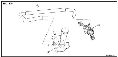
1. Reservoir hose
2. Reservoir tank
3. Master cylinder
LHD : Removal and Installation
REMOVAL
CAUTION:
• Keep painted surface on the body or other parts free of clutch fluid. If it
spills, wipe up immediately
and wash the affected area with water.
• Never disassemble clutch master cylinder.
1. Drain clutch fluid. Refer to CL-10, "RS5F92R : Draining" (RS5F92R) or CL-13, "RS6F94R : Draining" (RS6F94R).
2. Remove air cleaner case. Refer to EM-26, "Removal and Installation" (MR16DDT), EM-161, "Removal and Installation" (HR16DE), or EM-280, "Removal and Installation" (K9K).
3. Remove reservoir hose from reservoir tank and master cylinder.
4. Remove master cylinder rod end (
) from clutch pedal.
5. Pull up the lock pin (1) from connector of master cylinder (2) and separate clutch tube (3).
6. Rotate master cylinder clockwise by 45 degrees, and then remove master cylinder from the vehicle.

INSTALLATION
CAUTION:
Keep painted surface on the body or other parts free of clutch fluid. If it
spills, wipe up immediately
and wash the affected area with water.
1. Tilt master cylinder clockwise by 45 degrees (A) and insert it to the mounting hole. Rotate counterclockwise and secure it. At this time, nipple (1) is upward of the vehicle.
B : Mounting condition

2. Install master cylinder rod end to clutch pedal.
CAUTION:
Press master cylinder rod end into clutch pedal until it
stops.
3. Install reservoir hose to reservoir tank and master cylinder.
CAUTION:
Set reservoir hose with painted mark facing upward.
4. Press down the lock pin into connector of master cylinder until it stops.
5. Install clutch tube into connector of master cylinder until it stops.
6. For the next step and after, install in the reverse order of removal.
LHD : Inspection and Adjustment
INSPECTION AFTER INSTALLATION
• Check the fluid leakage and the fluid level. Refer to CL-10, "RS5F92R : Inspection" (RS5F92R) or CL-13, "RS6F94R : Inspection" (RS6F94R).
• Check the clutch pedal height, clutch pedal height at clutch disengagement, and clutch pedal play. Refer to CL-7, "Inspection and Adjustment".
• Check the clutch interlock switch position. (With push-button ignition switch system) Refer to CL-7, "Inspection and Adjustment".
• Check the clutch pedal position switch position. (With ASCD or with push-button ignition switch system) Refer to CL-7, "Inspection and Adjustment".
ADJUSTMENT AFTER INSTALLATION
• Adjust the clutch interlock switch position. (With push-button ignition switch system) Refer to CL-7, "Inspection and Adjustment".
• Adjust the clutch pedal position switch position. (With ASCD or with push-button ignition switch system) Refer to CL-7, "Inspection and Adjustment".
• Perform the air bleeding. Refer to CL-12, "RS5F92R : Air Bleeding" (RS5F92R) or CL-15, "RS6F94R : Air Bleeding" (RS6F94R).
RHD
RHD : Exploded View

1. Reservoir tank
2. Reservoir hose
3. Master cyl
RHD : Removal and Installation
REMOVAL
CAUTION:
• Keep painted surface on the body or other parts free of clutch fluid. If it
spills, wipe up immediately
and wash the affected area with water.
• Never disassemble clutch master cylinder.
1. Drain clutch fluid. Refer to CL-10, "RS5F92R : Draining" (RS5F92R) or CL-13, "RS6F94R : Draining" (RS6F94R).
2. Move the fuel feed tube and the fuel return hose aside not to interfere with
work. (K9K)
3. Remove reservoir hose from reservoir tank and master cylinder.
4. Remove master cylinder rod end (
) from clutch pedal.
5. Remove the engine room insulator.
6. Remove the cowl top extension. Refer to EXT-20, "Removal and Installation".

7. Pull up the lock pin (1) from connector of master cylinder (2) and separate clutch tube (3).
8. Rotate master cylinder clockwise by 45 degrees, and then remove master cylinder from the vehicle.

INSTALLATION
CAUTION
:
Keep painted surface on the body or other parts free of clutch fluid. If it
spills, wipe up immediately
and wash the affected area with water.
1. Tilt master cylinder clockwise by 45 degrees (A) and insert it to the mounting hole. Rotate counterclockwise and secure it. At this time, nipple (1) is upward of the vehicle.
B : Mounting condition

2. Install master cylinder rod end to clutch pedal.
CAUTION:
Press master cylinder rod end into clutch pedal until it
stops.
3. Install reservoir hose to reservoir tank and master cylinder.
4. Press down the lock pin into connector of master cylinder until it stops.
5. Install clutch tube into connector of master cylinder until it stops.
6. Install the fuel feed tube and the fuel return hose. (K9K) 7. Fill with clutch fluid. Refer to CL-11, "RS5F92R : Refilling" (RS5F92R) or CL-14, "RS6F94R : Refilling" (RS6F94R).
8. Install the engine room insulator.
9. Install the cowl top extension. Refer to EXT-20, "Removal and Installation".
RHD : Inspection and Adjustment
INSPECTION AFTER INSTALLATION
• Check the fluid leakage and the fluid level. Refer to CL-10, "RS5F92R : Inspection" (RS5F92R) or CL-13, "RS6F94R : Inspection" (RS6F94R).
• Check the clutch pedal height, clutch pedal height at clutch disengagement, and clutch pedal play. Refer to CL-7, "Inspection and Adjustment".
• Check the clutch interlock switch position. (With push-button ignition switch system) Refer to CL-7, "Inspection and Adjustment".
• Check the clutch pedal position switch position. (With ASCD or with push-button ignition switch system) Refer to CL-7, "Inspection and Adjustment".
ADJUSTMENT AFTER INSTALLATION
• Adjust the clutch interlock switch position. (With push-button ignition switch system) Refer to CL-7, "Inspection and Adjustment".
• Adjust the clutch pedal position switch position. (With ASCD or with push-button ignition switch system) Refer to CL-7, "Inspection and Adjustment".
• Perform the air bleeding. Refer to CL-12, "RS5F92R : Air Bleeding" (RS5F92R) or CL-15, "RS6F94R : Air Bleeding" (RS6F94R)
 Clutch pedal
LHD : Exploded View
1. Clutch pedal
2. Stopper rubber
3. Clip
4. Clutch interlock switch *1
5. Clutch pedal position switch *2
6. Pedal pad
7. Pedal stopper rubber
*1 : With push-button ...
 Clutch piping
Exploded View
RS5F92R
1. CSC (Concentric Slave Cylinder)
2. Clutch tube
3. Clutch damper
4. Bracket
5. Master cylinder
RS6F94R
1. CSC (Concentric Slave Cylinder)
2. Clutch tube
3. C ...
Other materials:
For frontal collision : When SRS is activated in a collision
CAUTION:
Due to varying models and option levels, not all parts listed in the chart below
apply to all vehicles.
WORK PROCEDURE
1. Before performing any of the following steps, ensure that all vehicle body
and structural repairs have been
completed.
2. Replace the diagnosis sensor unit.
...
Basic inspection
DIAGNOSIS AND REPAIR WORK FLOW
Work Flow
OVERALL SEQUENCE
DETAILED FLOW
1.GET INFORMATION FOR SYMPTOM
1. Get detailed information from the customer about the symptom (the
condition and the environment when
the incident/malfunction occurred).
2. Check operation condition of the function th ...
Compression pressure
Inspection
1. Warm up engine thoroughly. Then, stop it.
2. Release fuel pressure. Refer to EC-551, "Work Procedure".
3. Remove ignition coil and spark plug from each cylinder. Refer to EM-53,
"Exploded View".
4. Connect engine tachometer (not required in use of CONSULT-II ...
