Nissan Juke Service and Repair Manual : Camshaft valve clearance
Valve Clearance
CHECKING AND ADJUSTING THE VALVE CLEARANCE
1. Install the tappet.
2. Install the camshaft.
3. Install the camshaft brackets.
 : 11 N·m (1.1 kg-m, 8 ft-lb)
4. Place the valves of the cylinder concerned at the “end of exhaust - beginning of inlet” position and check the clearance (X).
NOTE
:
Dimension (Y) corresponds to the tappet thickness sizes (there
are 25 sizes at the service parts).


5. Compare the values recorded with the values specified, then replace the tappets which are not within tolerance.
Clearance, when the engine cold: Intake : 0.125 - 0.25 mm (0.0049 - 0.0098 in) Exhaust : 0.325 - 0.45 mm (0.0128 - 0.0177 in)
6. Remove the camshaft brackets.
7. Remove the camshaft.
8. Remove the tappet not within tolerance.
Determining dimension Y.
Set up the following assembly using KV113B0050 (Mot. 252-01) (Commercial service tool) or equivalent tool and dial gauge, then calibrate the gauge.
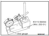
9. Raise the gauge extension (without modifying the position of the magnetic support/gauge assembly), then slide in the tappet to be measured.
• Note dimension (Y) and repeat the operation for the tappets where the valve clearance is not within tolerance.
• Refer to the Replacement Parts Catalogue for the vehicle concerned to select the various thicknesses of the tappet(s).
10. Check the valve clearance again.
11. Remove the camshaft brackets.
12. Remove the camshaft.
13. Remove the tappet(s) not within tolerance.

14. Grease the underside of the tappets and the camshaft brackets.
15. Degrease the gasket faces (of the cylinder head and brackets 1 and 6). They should be clean, dry and free from grease (in particular, remove finger marks).
16. Lay four beads of Loctite with a width of 1 mm (0.04 in) on brackets 1 and 6 of the cylinder head.
17. Install the camshaft.
18. Install the camshaft brackets (these are numbered from 1 to 6 and bearing (1) should be positioned on the flywheel end).
: 11 N·m (1.1 kg-m, 8 ft-lb)

 Basic inspection
...
 Symptom diagnosis
Noise, vibration and harshnesS (NVH) Troubleshooting
NVH Troubleshooting - Engine Noise
Use the Chart Below to Help You Find the Cause
of the Symptom
1. Locate the area where noise occurs.
2. C ...
Other materials:
P0122, P0123 TP SENSOR
DTC Logic
DTC DETECTION LOGIC
NOTE:
If DTC P0122 or P0123 is displayed with DTC P0643, first perform the trouble
diagnosis for DTC P0643.
Refer to EC-686, "DTC Logic".
DTC CONFIRMATION PROCEDURE
1.PRECONDITIONING
If DTC Confirmation Procedure has been previously conducted, alw ...
P0501, P2159 vehicle speed sensor
Description
ECM receives a rear wheel sensor signal from ABS actuator and electric unit
(control unit) via CAN communication
to switch combustion for the direct injection gasoline system. For the direct
injection gasoline system,
refer toEC-48, "DIRECT INJECTION GASOLINE SYSTEM : System ...
General maintenance
General Maintenance
General maintenance includes those items which should be checked during the
normal day-to-day operation
of the vehicle. They are essential if the vehicle is to continue operating
properly. The owners can perform
checks and inspections themselves or they can have their NISS ...
