Nissan Juke Service and Repair Manual : Camshaft valve clearance
Inspection and Adjustment
INSPECTION
Perform inspection as follows after removal, installation or replacement of camshaft or valve-related parts, or if there is unusual engine conditions regarding valve clearance.
1. Remove rocker cover. Refer to EM-53, "Exploded View".
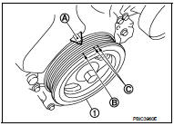
2. Measure the valve clearance with the following procedure: a. Set No. 1 cylinder at TDC of its compression stroke.
• Rotate crankshaft pulley (1) clockwise and align TDC mark (no paint) (B) to timing indicator (A) on front cover.
C : White paint mark (Not use for service)

• At the same time, check that both intake and exhaust cam
noses of No. 1 cylinder face inside (
 ) as shown in the figure.
1 : Camshaft (INT)
2 : Camshaft (EXH)
 : Engine front
• If they do not face inside, rotate crankshaft pulley once more (360 degrees) and align as shown in the figure.

b. Use a feeler gauge, measure the clearance between valve lifter and camshaft.
Valve clearance : Refer to EM-130, "Camshaft".

• By referring to the figure, measure the valve clearances at
locations marked “×” as shown in the table below [locations
indicated with black arrow ( ) in
the figure] with a feeler
gauge.
A : Exhaust side
B : No. 1 cylinder
C : No. 2 cylinder
D : No. 3 cylinder
E : No. 4 cylinder
F : Intake side
 : Engine front


c. Set No. 4 cylinder at TDC of its compression stroke.
• Rotate crankshaft pulley (1) one revolution (360 degrees) and align TDC mark (no paint) (B) to timing indicator (A) on front cover.
C : White paint mark (Not use for service)
• By referring to the figure, measure the valve clearance at locations
marked “×” as shown in the table below [locations indicated
with black arrow ( ) in the figure]
with a feeler gauge.
A : Exhaust side
B : No. 1 cylinder
C : No. 2 cylinder
D : No. 3 cylinder
E : No. 4 cylinder
F : Intake side
: Engine front


3. If out of standard, perform adjustment. Refer to “ADJUSTMENT”.
ADJUSTMENT
ADJUSTMENT • Perform adjustment depending on selected head thickness of valve lifter.
1. Remove camshaft. Refer to EM-78, "Exploded View".
2. Remove valve lifters at the locations that are out of the standard.
3. Measure the center thickness of the removed valve lifters with a micrometer (A).

4. Use the equation below to calculate valve lifter thickness for replacement.
Valve lifter thickness calculation: t = t1 + (C1 – C2) t = Valve lifter thickness to be replaced t1 = Removed valve lifter thickness C1 = Measured valve clearance C2 = Standard valve clearance: Intake : 0.30 mm (0.012 in) Exhaust : 0.33 mm (0.013 in)
• Thickness of new valve lifter (B) can be identified by stamp mark (A) on the reverse side (inside the cylinder).
• Stamp mark “302” indicates 3.02 mm (0.1189 in) in thickness.

NOTE
:
Available thickness of valve lifter: 26 sizes range 3.00 to 3.50 mm (0.1181 to
0.1378 in) in steps of 0.02
mm (0.0008 in) (when manufactured at factory). Refer to EM-130, "Camshaft".
5. Install the selected valve lifter.
6. Install camshaft. Refer to EM-78, "Exploded View".
7. Install timing chain and related parts. Refer to EM-67, "Exploded View".
8. Manually rotate crankshaft pulley a few rotations.
9. Check that the valve clearances is within the standard. Refer to “INSPECTION”.
10. Install remaining parts in the reverse order of removal.
11. Warm up the engine, and check for unusual noise and vibration.
 Basic inspection
...
 Compression pressure
Inspection
1. Warm up engine thoroughly. Then, stop it.
2. Release fuel pressure. Refer to EC-551, "Work Procedure".
3. Remove ignition coil and spark plug from each cylinder. Refer to ...
Other materials:
Before starting the engine
• Make sure the area around the vehicle is clear.
• Check fluid levels such as engine oil, coolant, brake fluid, and window washer
fluid as frequently as
possible, or at least whenever you refuel.
• Check that all windows and lights are clean.
• Visually inspect tires for their appearance and ...
Evaporative emission system
Inspection
1. Visually inspect EVAP vapor lines for improper attachment and for cracks,
damage, loose connections,
chafing and deterioration.
2. Check EVAP canister as follows:
a. Block port (B). Orally blow air through port (A).
Check that air flows freely through port (C).
b. Block port (A ...
P0087, P0088, P0090 FRP control system
DTC Logic
DTC DETECTION LOGIC
NOTE:
• If DTC P0087 or P0090 is displayed with DTC P1197, first perform the trouble
diagnosis for DTC
P1197.
• DTC P0087 or P0090 may be displayed when running out of gas.
DTC CONFIRMATION PROCEDURE
1.PRECONDITIONING
If DTC Confirmation Procedure has been p ...
