Nissan Juke Service and Repair Manual : C1140 actuator relay system
DTC Logic
DTC DETECTION LOGIC

DTC CONFIRMATION PROCEDURE
1.PRECONDITIONING
If “DTC CONFIRMATION PROCEDURE” has been previously conducted, always turn ignition switch OFF and wait at least 10 seconds before conducting the next test.
>> GO TO 2.
2.CHECK DTC DETECTION
 With CONSULT-III.
1. Turn the ignition switch OFF to ON.
2. Perform self-diagnosis for “ABS”.
Is DTC “C1140” detected? YES >> Proceed to BRC-60, "Diagnosis Procedure".
NO >> INSPECTION END
Diagnosis Procedure
1.CHECK CONNECTOR
1. Turn the ignition switch OFF.
2. Check ABS actuator and electric unit (control unit) harness connector for disconnection or looseness.
Is the inspection result normal? YES >> GO TO 3.
NO >> Repair or replace error-detected parts, securely lock the connector, and GO TO 2.
2.PERFORM SELF-DIAGNOSIS
Perform self-diagnosis for “ABS” again.
Is DTC “C1140” detected? YES >> GO TO 3.
NO >> INSPECTION END
3.CHECK ACTUATOR RELAY POWER SUPPLY
1. Turn the ignition switch OFF.
2. Disconnect ABS actuator and electric unit (control unit) harness connector.
3. Check voltage between ABS actuator and electric unit (control unit) harness connector and ground.

4. Turn the ignition switch ON.
CAUTION:
Never start engine.
5. Check voltage between ABS actuator and electric unit (control unit) harness connector and ground.
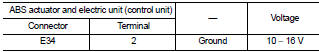
Is the inspection result normal? YES >> GO TO 5.
NO >> GO TO 4.
4.CHECK ACTUATOR RELAY POWER SUPPLY CIRCUIT
1. Turn the ignition switch OFF.
2. Check 40 A fusible link (F).
3. Check continuity and short circuit between ABS actuator and electric unit (control unit) harness connector terminal (2) and 40 A fusible link (F).
Is the inspection result normal? YES >> Perform trouble diagnosis for battery power supply. Refer to PG-10, "Wiring Diagram - BATTERY POWER SUPPLY -".
NO >> Repair or replace error-detected parts.
5.CHECK ACTUATOR RELAY GROUND CIRCUIT
1. Turn the ignition switch OFF.
2. Check continuity between ABS actuator and electric unit (control unit) harness connector and the ground.

Is the inspection result normal? YES >> GO TO 6.
NO >> Repair or replace error-detected parts.
6.CHECK TERMINAL
Check ABS actuator and electric unit (control unit) pin terminals for damage or loose connection with harness connector.
Is the inspection result normal? YES >> Replace ABS actuator and electric unit (control unit). Refer to BRC-90, "Removal and Installation".
NO >> Repair or replace error-detected parts.
 C1121, C1123, C1125, C1127 ABS out valve system
DTC Logic
DTC DETECTION LOGIC
DTC CONFIRMATION PROCEDURE
1.PRECONDITIONING
If “DTC CONFIRMATION PROCEDURE” has been previously conducted, always turn
ignition switch OFF and
wait at least 10 ...
 U1000 can comm circuit
Description
CAN (Controller Area Network) is a serial communication line for real time
application. It is an on-vehicle multiplex
communication line with high data communication speed and excellen ...
Other materials:
Squeak and rattle trouble diagnoses
Work Flow
CUSTOMER INTERVIEW
Interview the customer if possible, to determine the conditions that exist
when the noise occurs. Use the Diagnostic
Worksheet during the interview to document the facts and conditions when the
noise occurs and any of
the customer's comments; refer to DLK-139, &q ...
Rear wiper motor circuit
Component Function Check
1.CHECK REAR WIPER ON OPERATION
CONSULT-III ACTIVE TEST
1. Select “RR WIPER” of BCM active test item.
2. With operating the test item, check rear wiper operation.
On : Rear wiper ON operation
Off : Stop the rear wiper.
Is rear wiper operation normally?
YES >> R ...
Rear suspension beam
Exploded View
1. Rear suspension beam
2. Rear suspension arm bracket
: Always replace after every
disassembly.
: N·m (kg-m, ft-lb)
Removal and Installation
REMOVAL
1. Remove tires. Refer to WT-7, "Removal and Installation".
2. Drain brake fluid. Refer to BR-12, "Draining& ...
