Nissan Juke Service and Repair Manual : Brake pedal position switch
Component Function Check
1.CHECK BRAKE PEDAL POSITION SWITCH FUNCTION
 With CONSULT-III
1. Turn ignition switch ON.
2. Select “BRAKE SW1” in “DATA MONITOR” mode of “ENGINE” using CONSULT-III.
3. Check “BRAKE SW1” indication as per the following conditions.

 Without CONSULT-III
1. Turn ignition switch ON.
2. Check the voltage between ECM harness connector terminals as per the following.

Is the inspection result normal? YES >> INSPECTION END
NO >> Proceed to EC-425, "Diagnosis Procedure".
Diagnosis Procedure
1.CHECK BRAKE PEDAL POSITION SWITCH POWER SUPPLY
1. Turn ignition switch OFF.
2. Disconnect brake pedal position switch harness connector.
3. Turn ignition switch ON.
4. Check the voltage between brake pedal position switch harness connector and ground.

*1: LHD models or RHD with CVT models *2: RHD with M/T models
Is the inspection result normal? YES >> GO TO 2.
NO >> Perform the trouble diagnosis for power supply circuit.
2.CHECK BRAKE PEDAL POSITION SWITCH INPUT SIGNAL CIRCUIT
1. Turn ignition switch OFF.
2. Disconnect ECM harness connector.
3. Check the continuity between brake pedal position switch harness connector and ECM harness connector.
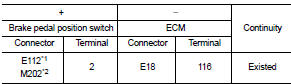
*1: LHD models or RHD with CVT models *2: RHD with M/T models
4. Also check harness for short to ground and to power.
Is the inspection result normal? YES >> GO TO 3.
NO >> Repair or replace error-detected parts.
3.CHECK BRAKE PEDAL POSITION SWITCH
Check the brake pedal position switch. Refer to EC-426, "Component Inspection (Brake Pedal Position Switch)" Is the inspection result normal? YES >> Check intermittent incident. Refer to GI-42, "Intermittent Incident".
NO >> Replace brake pedal position switch. Refer to BR-20, "Exploded View" (LHD) or BR-88, "Exploded View" (RHD)
Component Inspection (Brake Pedal Position Switch)
1.CHECK BRAKE PEDAL POSITION SWITCH-I
1. Turn ignition switch OFF.
2. Disconnect brake pedal position harness connector.
3. Check the continuity between brake pedal position switch terminals as per the following conditions.

Is the inspection result normal? YES >> INSPECTION END
NO >> GO TO 2.
2.CHECK BRAKE PEDAL POSITION SWITCH-II
1. Adjust brake pedal position switch installation. Refer to BR-9, "Inspection and Adjustment" (LHD) or BR- 77, "Inspection and Adjustment" (RHD).
2. Check the continuity between brake pedal position switch terminals as per the following conditions.

Is the inspection result normal? YES >> INSPECTION END
NO >> Replace brake pedal position switch. Refer to BR-20, "Exploded View" (LHD) or BR-88, "Exploded View" (RHD).
 Refrigerant pressure sensor
Component Function Check
1.CHECK REFRIGERANT PRESSURE SENSOR OVERALL FUNCTION
1. Start engine and warm it up to normal operating temperature.
2. Turn A/C switch and blower fan switch ON.
3. Check ...
 Clutch pedal position switch
Component Function Check
1.CHECK FOR CLUTCH PEDAL POSITION SWITCH FUNCTION
1. Turn ignition switch ON.
2. Check the voltage between ECM harness connector and ground.
Is the inspection result nor ...
Other materials:
Auto retractable door mirror circuit
Component Function Check
1.CHECK FUNCTION
1. Turn the door mirror open/close switch to “AUTO”.
2. Turn ignition switch ON.
3. Select “INTELLIGENT KEY” of “BCM” using CONSULT-III.
4. Select “RETRACTABLE MIRROR” in “ACTIVE TEST” mode.
5. Touch “On” check that it works normally.
Is the inspect ...
B1116 satellite sensor RH
DTC Logic
DTC DETECTION LOGIC
DTC CONFIRMATION PROCEDURE
1.CHECK SELF-DIAG RESULT
With CONSULT-III
1. Turn ignition switch ON.
2. Perform “Self Diagnostic Result” mode of “AIR BAG” using CONSULT-III.
Without CONSULT-III
1. Turn ignition switch ON.
2. Check the air bag warning lamp statu ...
Reference Value
VALUES ON THE DIAGNOSIS TOOL
Remarks:
• Specification data are reference values.
• Specification data are output/input values
which are detected or supplied by the ECM at the connector.
* Specification data may not be directly related to their components
signals/values/operations.
I.e. ...
