Nissan Juke Service and Repair Manual : Brake fluid level switch
Component Function Check
1.CHECK BRAKE FLUID LEVEL SWITCH OPERATION
When the brake fluid is full or empty. Then check that the brake warning lamp in the combination meter turns ON/OFF correctly.
Is the inspection result normal? YES >> INSPECTION END
NO >> Proceed to BRC-72, "Diagnosis Procedure".
Diagnosis Procedure
1.CHECK BRAKE FLUID LEVEL SWITCH CIRCUIT
1. Turn the ignition switch OFF.
2. Disconnect brake fluid level switch harness connector.
3. Disconnect combination meter harness connector.
4. Check continuity between brake fluid level switch harness connector and combination meter harness connector.

5. Check continuity between brake fluid level switch harness connector and ground.

Is the inspection result normal? YES >> GO TO 2.
NO >> Repair or replace error-detected parts.
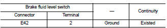
2.CHECK BRAKE FLUID LEVEL SWITCH GROUND CIRCUIT
Check continuity between brake fluid level switch harness connector and ground.
Is the inspection result normal? YES >> GO TO 3.
NO >> Repair or replace error-detected parts.
3.CHECK BRAKE FLUID LEVEL SWITCH
Check brake fluid level switch. Refer to BRC-73, "Component Inspection".
Is the inspection result normal? YES >> GO TO 4.
NO >> Replace reservoir tank.
• LHD: Refer to BR-44, "Disassembly and Assembly".
• RHD: Refer to BR-109, "Disassembly and Assembly".
4.CHECK COMBINATION METER
Check combination meter. Refer to MWI-23, "CONSULT-III Function".
Is the inspection result normal?
YES >> Check each pin terminals for damage or loose connection with harness connector. If any items are damaged, repair or replace error-detected parts.
NO >> Repair or replace combination meter. Refer to MWI-69, "Removal and Installation".
Component Inspection
1.CHECK BRAKE FLUID LEVEL SWITCH
1. Turn the ignition switch OFF.
2. Disconnect brake fluid level switch harness connector.
3. Check continuity between brake fluid level switch harness connector

Is the inspection result normal? YES >> INSPECTION END
NO >> Replace reservoir tank.
• LHD: Refer to BR-44, "Disassembly and Assembly".
• RHD: Refer to BR-109, "Disassembly and Assembly".
 Parking brake switch
Component Function Check
1.CHECK PARKING BRAKE SWITCH OPERATION
Operate the parking brake lever. Then check that the brake warning lamp in
the combination meter turns ON/
OFF correctly.
Is the ...
 ABS warning lamp
Component Function Check
1.CHECK ABS WARNING LAMP FUNCTION
Check that ABS warning lamp in combination meter turns ON for approx. 1
second after ignition switch is
turned ON.
CAUTION:
Never st ...
Other materials:
B261F ASCD clutch switch
DTC Logic
DTC DETECTION LOGIC
NOTE:
• If DTC B261F is displayed with DTC U1000, first perform the trouble diagnosis
for DTC U1000. Refer to
BCS-83, "DTC Logic".
• If DTC B261F is displayed with DTC U1010, first perform the trouble diagnosis
for DTC U1010. Refer to
BCS-84, "D ...
Exterior lighting system symptoms
Without daytime running light system
WITHOUT DAYTIME RUNNING LIGHT SYSTEM : Symptom Table
CAUTION:
Perform the self-diagnosis with CONSULT-III before the symptom diagnosis.
Perform the trouble diagnosis
if any DTC is detected.
With daytime running light system
WITH DAYTIME RUNNING LIGHT ...
U0122 Vehicle dynamics control
module
Description
CAN (Controller Area Network) is a serial communication line for real time
application. It is an on-vehicle multiplex
communication line with high data communication speed and excellent error
detection ability. Many electronic
control units are equipped onto a vehicle, and each c ...
