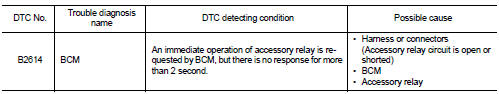
Nissan Juke Service and Repair Manual : B2614 ACC relay circuit
DTC Logic
DTC DETECTION LOGIC
DTC CONFIRMATION PROCEDURE
1.PERFORM DTC CONFIRMATION PROCEDURE
1. Turn the power supply position to ACC under the following conditions, and wait for 2 second or more.
CVT models
- Selector lever is in the P or N position
- Do not depress brake pedal
M/T models
- Do not depress clutch pedal
2. Check “Self-diagnosis result” of BCM with CONSULT-III.
Is DTC detected? YES >> Go to PCS-91, "Diagnosis Procedure".
NO >> INSPECTION END
Diagnosis Procedure
1.CHECK ACCESSORY RELAY POWER SUPPLY-1
1. Turn ignition switch OFF.
2. Disconnect accessory relay.
3. Check voltage between accessory relay harness connector and ground.

Is the inspection result normal? YES >> GO TO 3.
NO >> GO TO 2.
2.CHECK ACCESSORY RELAY POWER SUPPLY CIRCUIT
1. Turn ignition switch OFF.
2. Disconnect BCM connector.
3. Check continuity between accessory relay harness connector and BCM harness connector.

4. Check continuity between accessory relay harness connector and ground.

Is the inspection result normal? YES >> Replace BCM. Refer to BCS-93, "Removal and Installation".
NO >> Repair or replace harness.
3.CHECK ACCESSORY RELAY GROUND CIRCUIT
1. Turn ignition switch OFF.
2. Check continuity between accessory relay harness connector and ground.

Is the inspection result normal? YES >> GO TO 4.
NO >> Repair accessory relay ground circuit.
4.CHECK ACCESSORY RELAY POWER SUPPLY CIRCUIT-2
1. Turn ignition switch ACC.
2. Check voltage between accessory relay harness connector and ground.

Is the inspection result normal? YES >> GO TO 5.
NO >> Check continuity open or short between accessory relay and battery.
5.CHECK ACCESSORY RELAY
Refer to PCS-92, "Component Inspection".
Is the inspection result normal? YES >> GO TO 6.
NO >> Replace accessory relay.
6.CHECK INTERMITTENT INCIDENT
Refer to GI-42, "Intermittent Incident".
>> INSPECTION END
Component Inspection
1.CHECK ACCESSORY RELAY
1. Turn ignition switch OFF.
2. Remove accessory relay.
3. Check the continuity between accessory relay terminals.

Is the inspection result normal? YES >> INSPECTION END
NO >> Replace accessory relay


 B2615 blower relay circuit
DTC Logic
DTC DETECTION LOGIC
DTC CONFIRMATION PROCEDURE
1.PERFORM DTC CONFIRMATION PROCEDURE
1. Turn ignition switch ON under the following conditions, and wait for 1
second or more.
CVT m ...
Other materials:
Door lock actuator
Driver side
DRIVER SIDE : Component Function Check
1.CHECK FUNCTION
1. Select “DOOR LOCK” of “BCM” using CONSULT-III.
2. Select “DOOR LOCK” in “ACTIVE TEST” mode.
3. Check that the function operates normally according to the following
conditions.
Is the inspection result normal?
YES >& ...
Power supply and ground circuit
AUDIO UNIT
AUDIO UNIT : Diagnosis Procedure
1.CHECK FUSE
Check for blown fuses.
Is inspection result OK?
YES >> GO TO 2.
NO >> Be sure to eliminate cause of malfunction before installing new fuse.
2.CHECK POWER SUPPLY CIRCUIT
Check voltage between audio unit harness connect ...
ECU diagnosis information
ECM
Reference Value
TERMINAL LAYOUT
PHYSICAL VALUES
NOTE:
• ECM is located in the engine room left side near battery.
• When disconnecting ECM harness connector (1), loosen (B) it with
levers as far as they will go as shown in the figure.
2 : ECM
A : Fasten
• Pulse signal is measured by ...
